| Battery technology | Lithium-Ionen |
| Battery voltage class | 48 V |
| Battery capacity | 14,1 kWh |
| Battery weight | 132 kg |
| On-board charging capacity (max.) | 3 kW |
| Loading time (0-100%) | 4 - 6* h |
| Loading time (20-80%) | 2,9* h |
| Running time up to | 3,0** h |
| Battery technology | Lithium-Ionen |
| Battery voltage class | 48 V |
| Battery capacity | 18,7 kWh |
| Battery weight | 148 kg |
| On-board charging capacity (max.) | 6 kW |
| Loading time (0-100%) | 3 - 8* h |
| Loading time (20-80%) | 1,9* h |
| Running time up to | 4,6** h |
| Battery technology | Lithium-Ionen |
| Battery voltage class | 48 V |
| Battery capacity | 23,4 kWh |
| Battery weight | 165 kg |
| On-board charging capacity (max.) | 6 kW |
| Loading time (0-100%) | 4 - 10* h |
| Loading time (20-80%) | 2,4* h |
| Running time up to | 6,6** h |
| Motor traction drive (EN60034-1) | 6,5 kW |
| Motor work hydraulics (EN60034-1) | 8,5 kW |
| Operating voltage | 12 V |
| Operating weight | 2.400 - 2.580 kg |
| Tipping load with bucket – machine straight, loading frame horizontal | 1.430 - 1.780 kg |
| Tipping load with bucket – machine pivoted, loading frame horizontal | 1.200 - 1.480 kg |
| Tipping load with bucket - machine straight, loading frame in lowest position | 2.030 - 2.860 kg |
| Tipping load with bucket - machine pivoted, loading frame in lowest position | 1.720 - 2.400 kg |
| Tipping load with pallet fork – machine straight, loading frame horizontal | 1.140 - 1.390 kg |
| Tipping load with pallet fork – machine pivoted, loading frame horizontal | 950 - 1.150 kg |
| Tipping load with pallet fork - machine straight, transport position | 1.330 - 1.680 kg |
| Tipping load with pallet fork - machine pivoted, transport position | 1.120 - 1.410 kg |
| Driver's cab | FSD (eps, Kabine) |
| Tank capacity for hydraulic oil | 20 l |
| Type of drive | elektrisch |
| Drive unit | Gelenkwelle |
| Speed levels | 1 |
| Axle | T80 |
| Travel speed Standard | 0-15 km/h |
| Operating brake | Trommelbremse auf alle vier Räder wirkend |
| Parking brake | elektrisch |
| Work hydraulics discharge volume (max.) | 36 l/min |
| Work hydraulics working pressure (max.) | 225 bar |
| Kinematics type | P |
| Lifting cylinder | 1 |
| Tipping cylinder | 1 |
| Quick change system | hydraulisch |
| Steering type | Hydraulische Knick-Pendellenkung |
| Steering cylinder | 1 |
| Oscillating angle | ± 10 Grad |
| Average sound power level LwA (operator's canopy) | 82,9 dB(A) |
| Guaranteed sound power level LwA (operator's canopy) | 85 dB(A) |
| Specified sound pressure level LpA (operator's canopy) | 68 dB(A) |
| Average sound power level LwA (cabin) | 82,9 dB(A) |
| Guaranteed sound power level LwA (cabin) | 85 dB(A) |
| Specified sound pressure level LpA (cabin) | 70 dB(A) |
|
FSD = Fahrerschutzdach Kipplastberechnung nach ISO 14397 *Die Ladezeit hängt von den unterschiedlichen Lademöglichkeiten ab. Onboard Ladegerät 3 kW (Standard), mit zusätzlichem Onboard Lagegerät insgesamt 6 kW (Option). Es stehen folgende Ladestecker zur Verfügung: 230 V / 10 A Schuko, 230 V / 16 A CEE (blau, 3-polig), 400 V / 16 A CEE (rot, Drehstrom, 5-polig), 400 V / 16 A (Typ 2 Stecker Wallbox, IEC 62196) und weitere Adapter Stecker. **Die Laufzeiten der Batterie sind von den jeweiligen Einsatzbedingungen, der Arbeitsaufgabe und der Fahrweise abhängig. Das kann dazu führen, dass auch eine längere Laufzeit erreicht werden kann. Die angegebenen Laufzeiten können im Extremfall aber auch unterschritten werden. Die angegebenen Laufzeiten beziehen sich auf ununterbrochenen Betrieb und Arbeiten mit der Maschine. |
When comparing tipping loads and lift capacities from different manufacturers, make sure that they have been determined in accordance with the ISO 14397-1 and 2 standards!
General Information
Attention: The tipping load changes depending on the various equipment features of a machine (e.g. operator’s platform/cab, rear weight, engine, tires, etc.). The net weight of the various attachments naturally also plays a role here.
Important to note
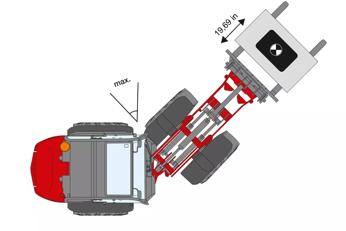
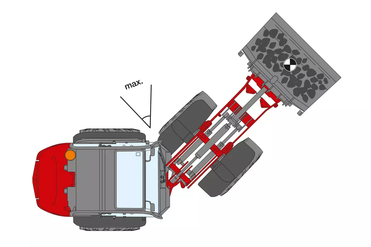
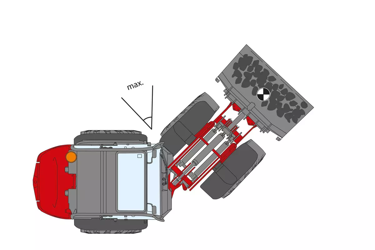
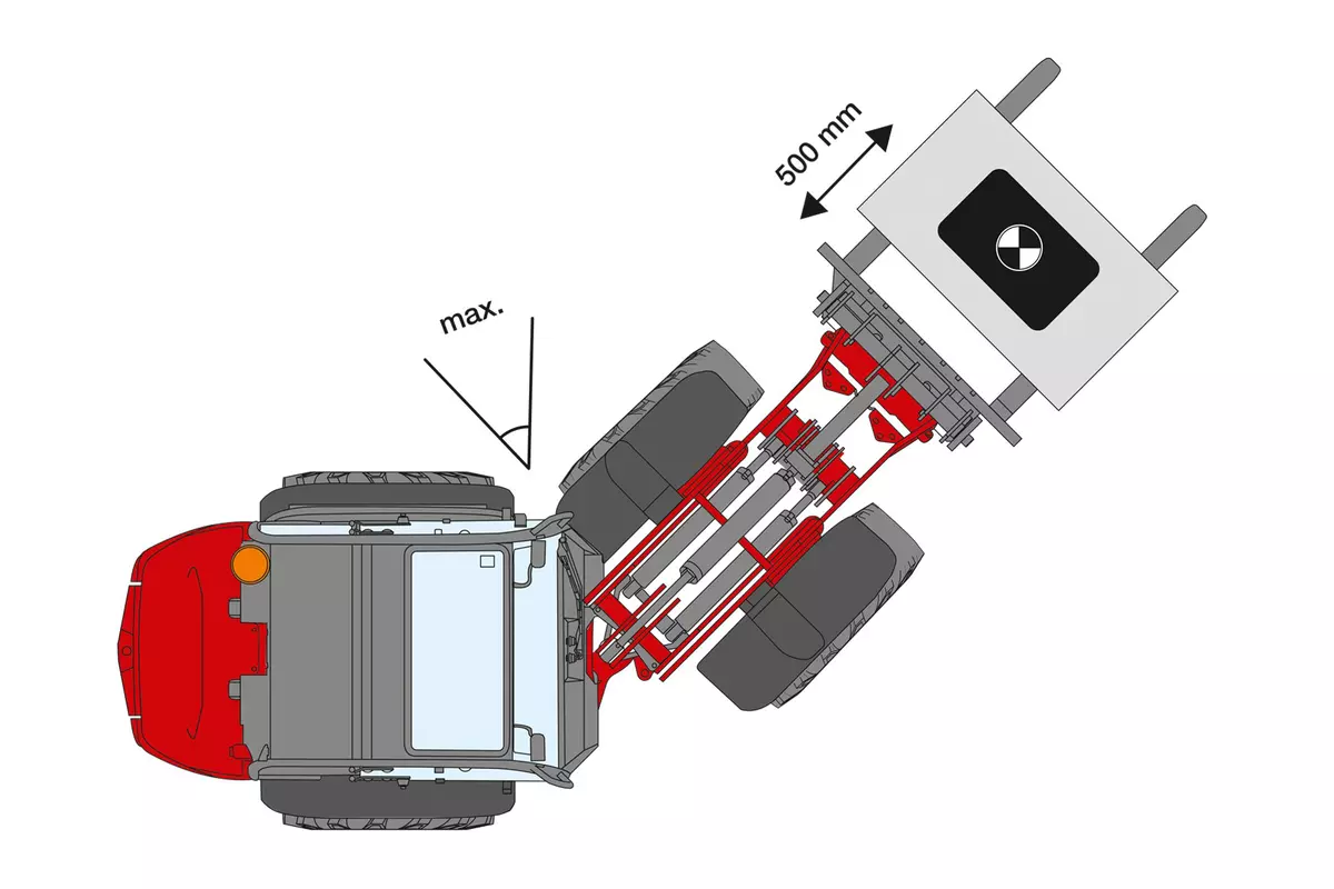
Good to know: Tipping loads determined in the buckled state are highly dependent on the buckling angle of the machine. Weidemann determines these values in the fully folded state. When comparing with other manufacturers, please note the kink angle used!
When comparing tipping loads and lift capacities from different manufacturers, make sure that they have been determined in accordance with the ISO 14397-1 and 2 standards!
General Information
Attention: The tipping load changes depending on the various equipment features of a machine (e.g. operator’s platform/cab, rear weight, engine, tires, etc.). The net weight of the various attachments naturally also plays a role here.
Important to note
Good to know: Tipping loads determined in the buckled state are highly dependent on the buckling angle of the machine. Weidemann determines these values in the fully folded state. When comparing with other manufacturers, please note the kink angle used!
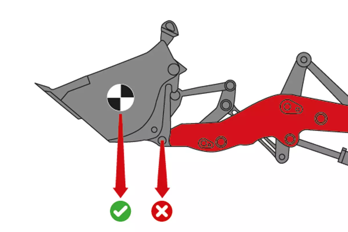
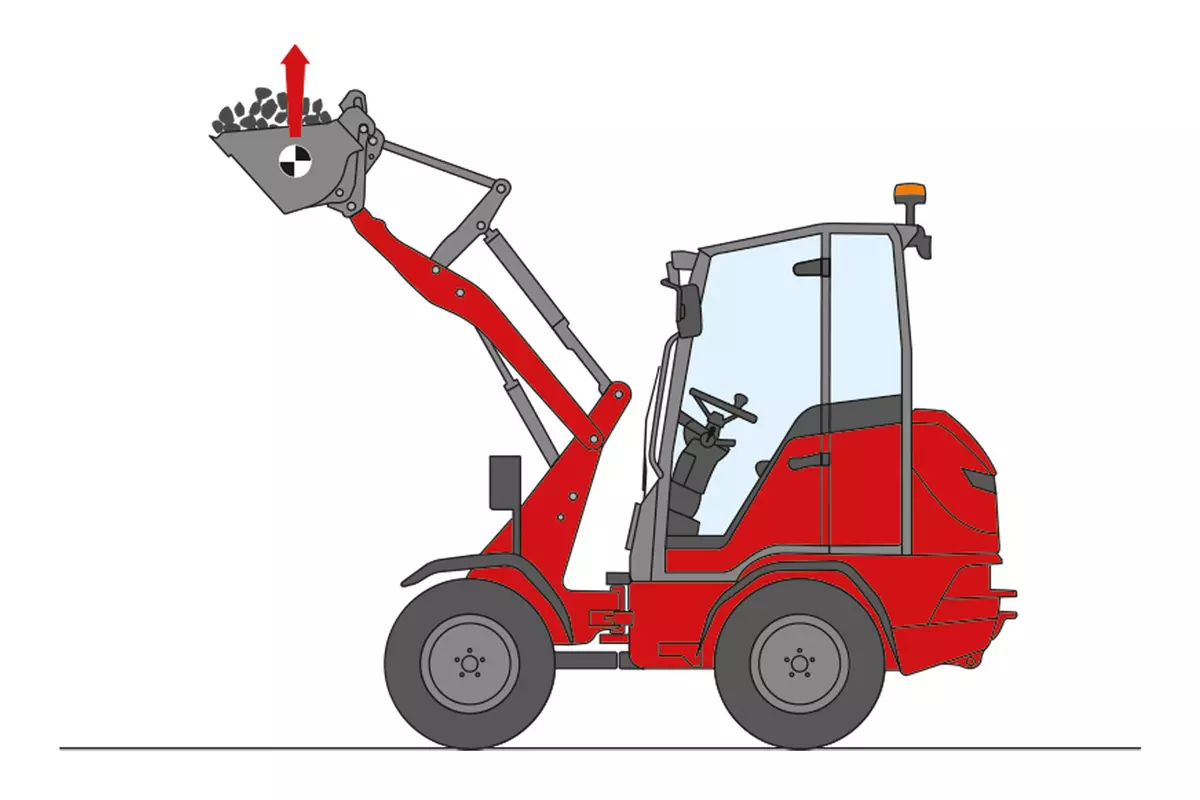
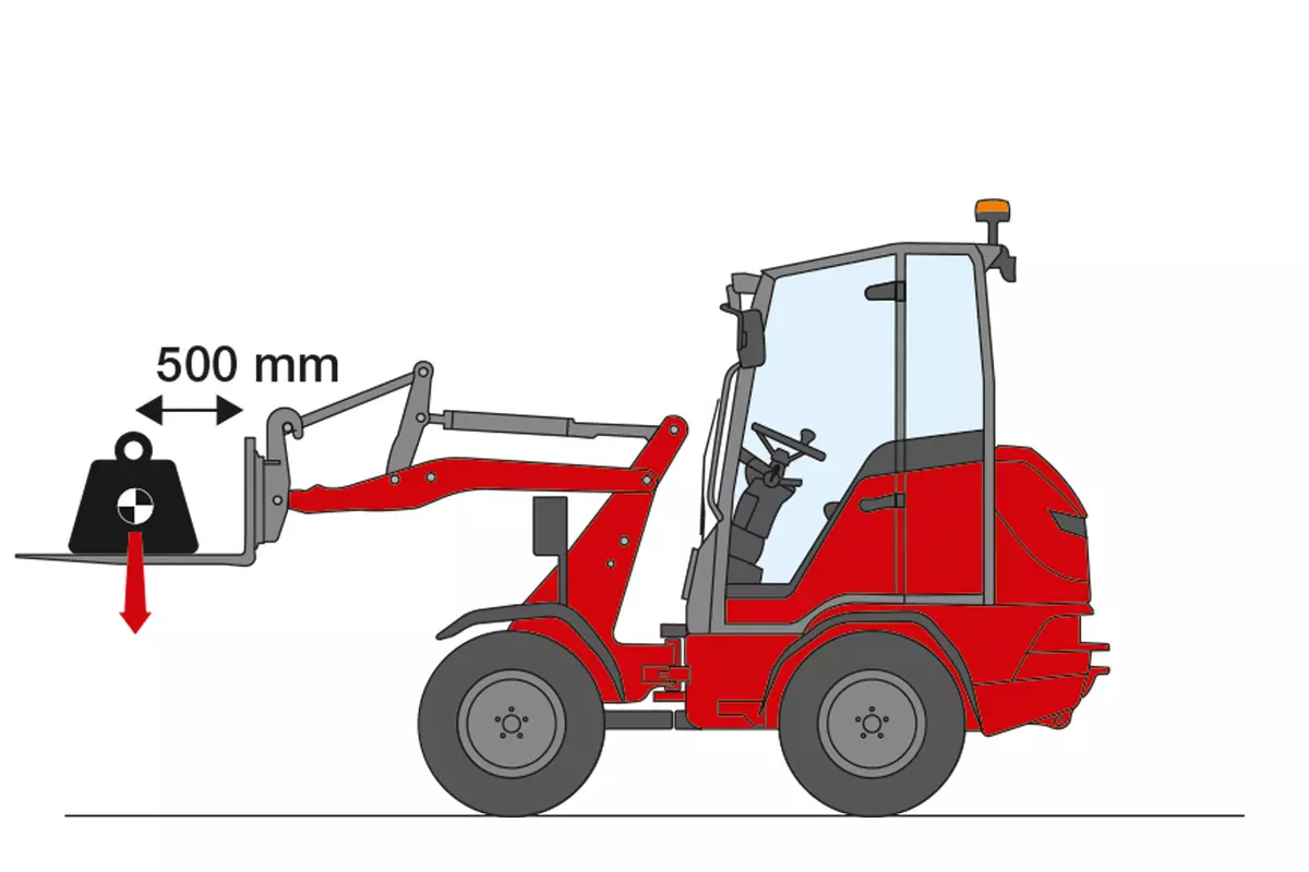
Weidemann determines these values in accordance with the standard at the center of gravity of the bucket – not at the pivot point!
|
|
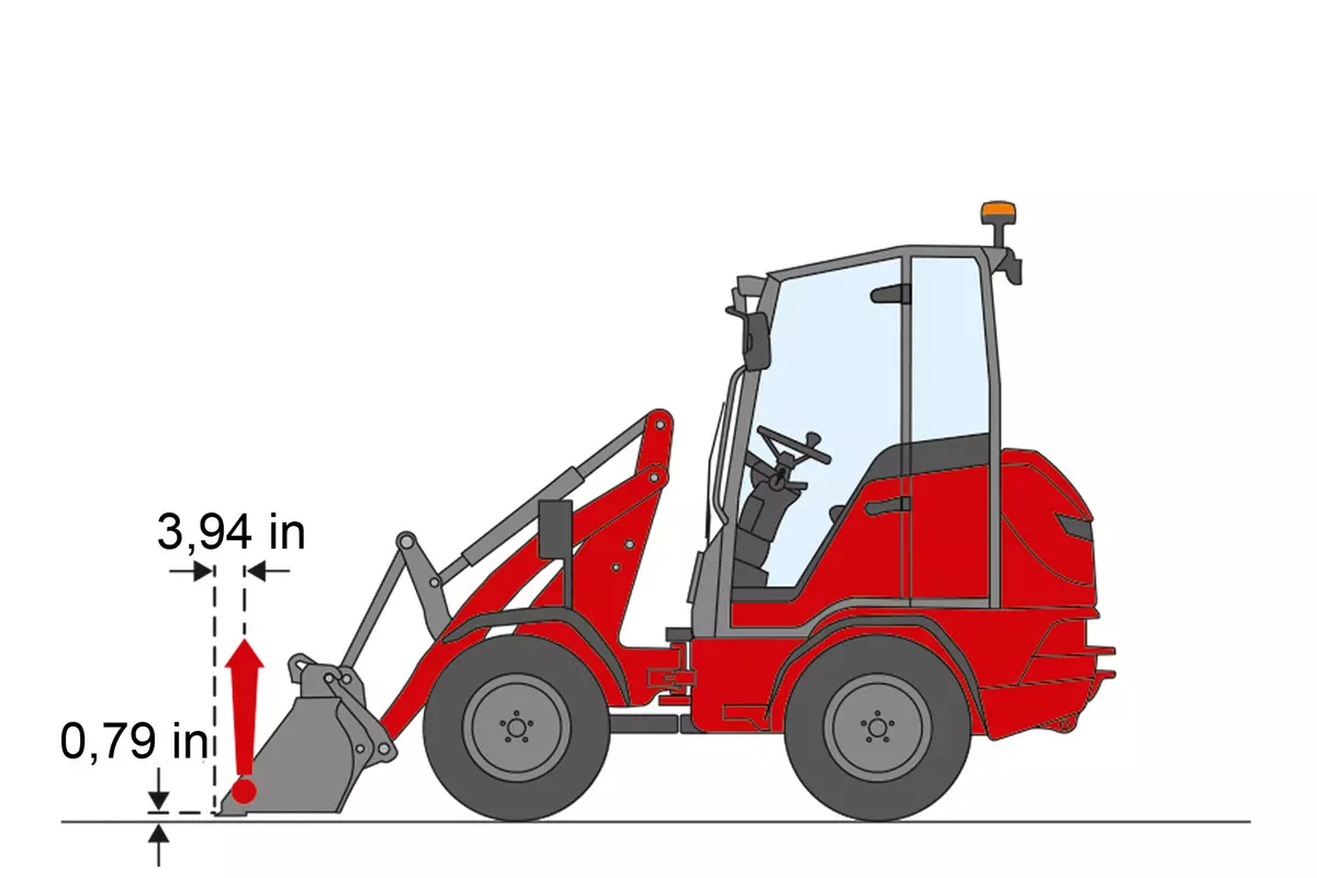
The maximum lift capacity in the bucket’s center of gravity is measured by Weidemann as follows:
|
|
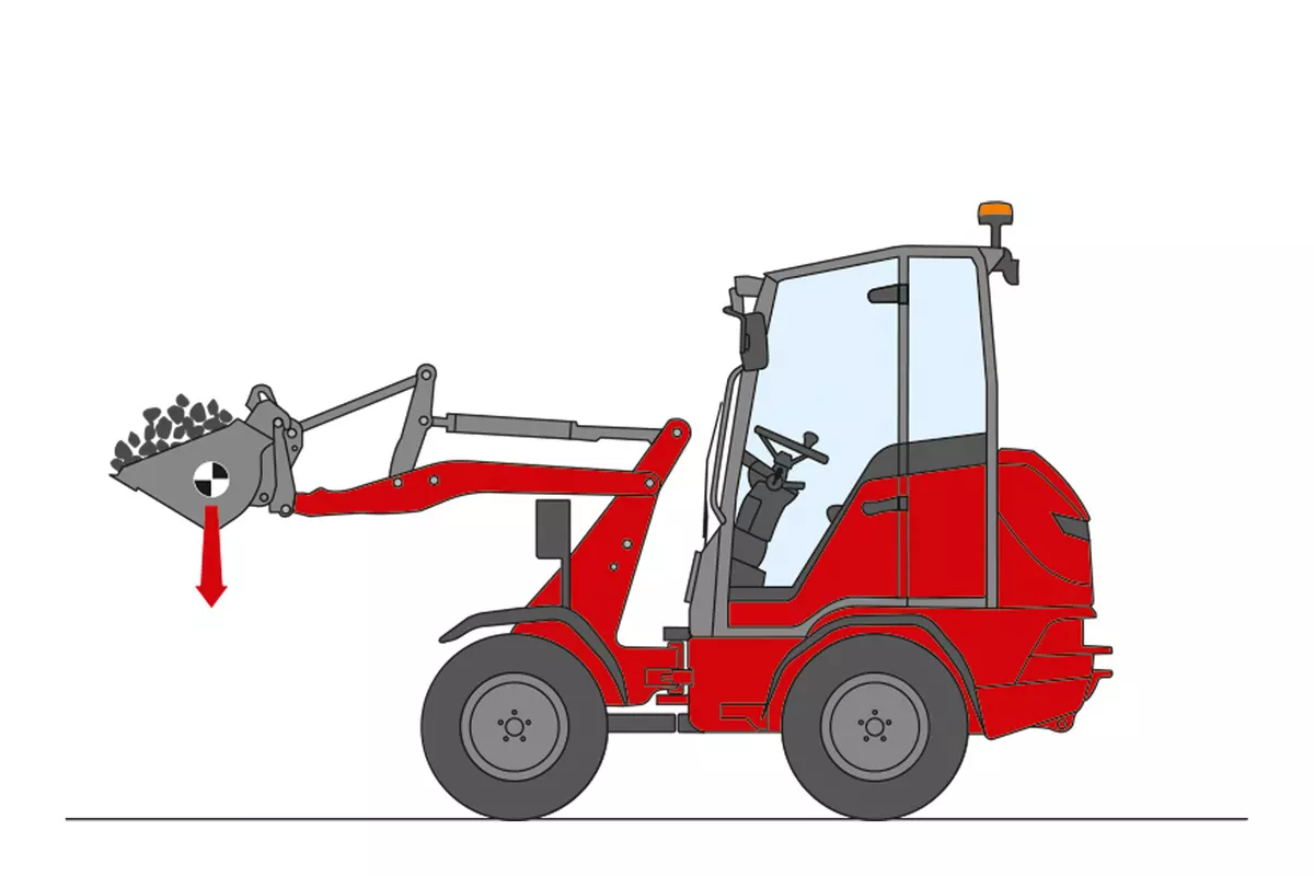
The maximum tear out force on the below bucket edge is measured by Weidemann according to the standard ISO 14397-2, this means:

|
|
The maximum load weight of a machine is known as the tipping load. This is achieved when the rear wheels of the machine lose contact with the ground. The tipping load is measured by Weidemann according to the standard ISO 14397-1, this means:
|
|
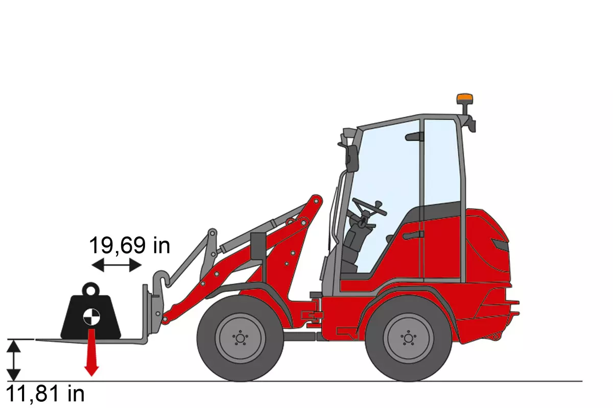
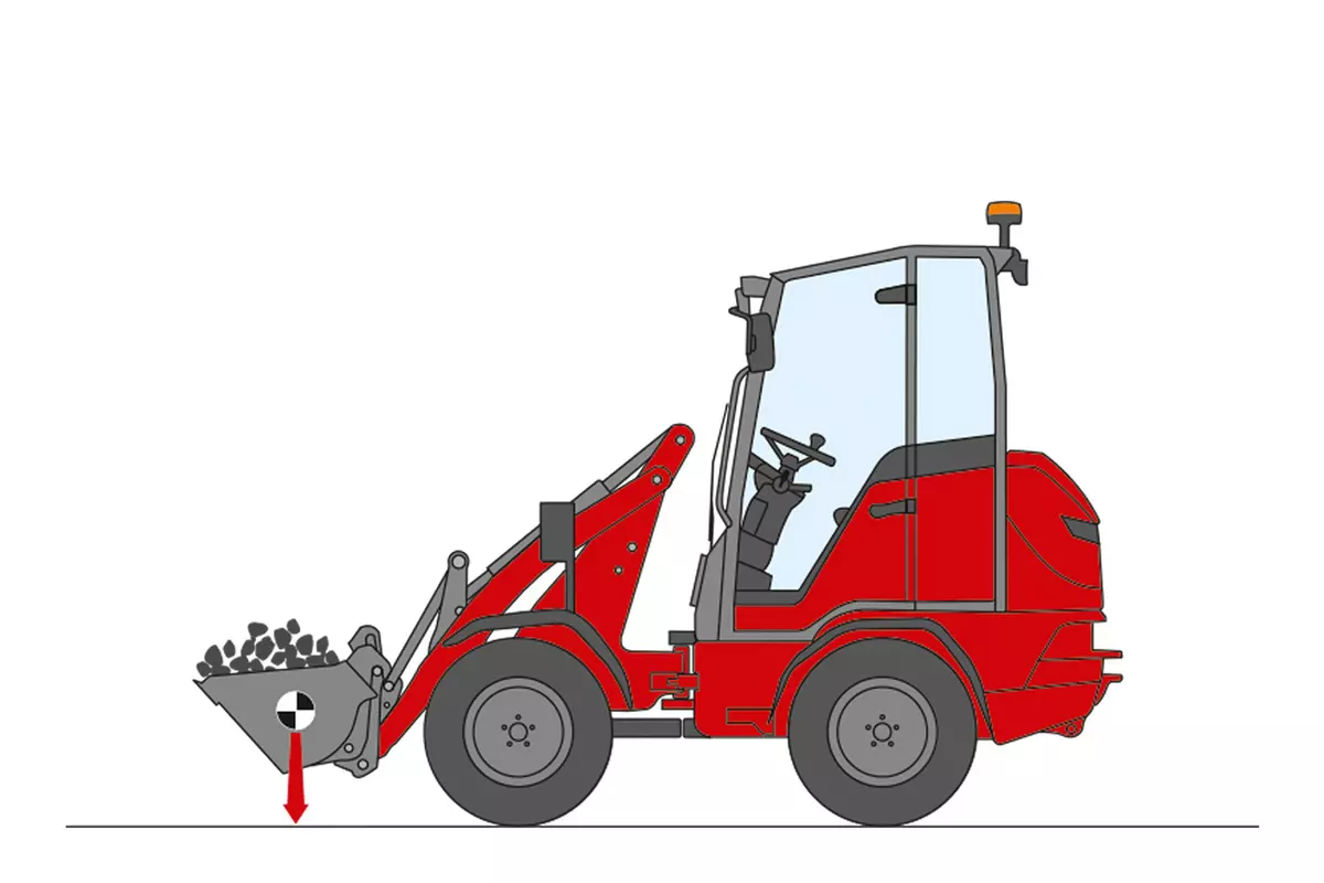
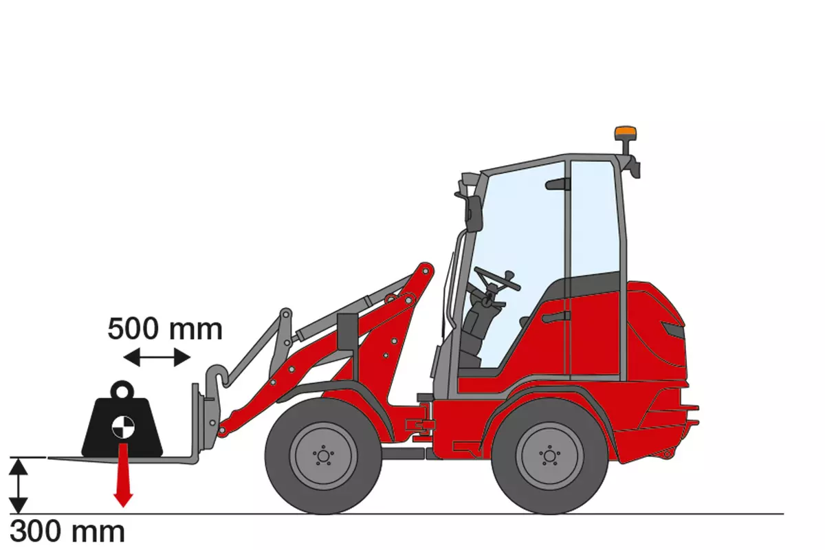
The maximum load weight of a machine is known as the tipping load. This is achieved when the rear wheels of the machine lose contact with the ground. The tipping load in lowest position is measured by Weidemann as follows:
|
|
The maximum load weight of a machine is known as the tipping load. This is achieved when the rear wheels of the machine lose contact with the ground. The tipping load is measured by Weidemann according to the standard ISO 14397-1, this means:

|
|
The maximum load weight of a machine is known as the tipping load. This is achieved when the rear wheels of the machine lose contact with the ground. The tipping load in transport position is measured by Weidemann as follows:
|