


Thank you
Your request has been sent successfully
| Engine manufacturer | Deutz |
| Motor type | TD 2.9 L4 S5 |
| Cylinder | 4 |
| Drive output | 45 kW |
| Drive output | 61 PS |
| At max. rpm | 2,300 U/min |
| Cylinder capacity | 2,900 cm³ |
| Type of coolant | Water |
| Exhaust standard level | V |
| Exhaust aftertreatment | DOC/DPF |
| Average sound power level LwA (cabin) | 98.8 dB(A) |
| Guaranteed sound power level LwA (cabin) | 100 dB(A) |
| Specified sound pressure level LpA (cabin) | 74 dB(A) |
| Engine manufacturer | Deutz |
| Motor type | TCD 2.9 L4 S5 |
| Cylinder | 4 |
| Drive output | 55.4 kW |
| Drive output | 75 PS |
| At max. rpm | 2,300 U/min |
| Cylinder capacity | 2,900 cm³ |
| Type of coolant | Water/charge air |
| Exhaust standard level | V |
| Exhaust aftertreatment | DOC/DPF |
| Average sound power level LwA (cabin) | 100 |
| Guaranteed sound power level LwA (cabin) | 101 |
| Specified sound pressure level LpA (cabin) | 77 |
| Operating voltage | 12 V |
| Battery | 100 Ah |
| Alternator | 95 A |
| Operating weight | 4,300 kg |
| Tipping load with bucket – machine straight, loading frame horizontal | 3,719 kg |
| Tipping load with bucket – machine pivoted, loading frame horizontal | 3,113 kg |
| Tipping load with pallet fork – machine straight, loading frame horizontal | 3,170 kg |
| Tipping load with pallet fork – machine pivoted, loading frame horizontal | 2,662 kg |
| Driver's cab | Cab |
| Tank capacity for fuel | 65 l |
| Tank capacity for hydraulic oil | 50 l |
| Type of drive | Hydrostatic |
| Drive unit | universal joint shaft |
| Speed levels | 2 |
| Axle | PA 1200 |
| Travel speed Standard | 0-20 km/h |
| Travel speed Option 1 | 0-28 km/h |
| Operating brake | Hydrostatic drive system acting on all 4 wheels (wear-free) |
| Parking brake | Service and parking brake in the drive train acts on all 4 wheels |
| Differential lock | 100 % front axle + rear axle |
| Drive hydraulics working pressure (max.) | 450 bar |
| Work hydraulics discharge volume (max.) | 57,5 (74-115) l/min |
| Work hydraulics working pressure (max.) | 210 bar |
| Kinematics type | PZ |
| Lifting cylinder | 2 |
| Tipping cylinder | 1 |
| Quick change system | hydraulic |
| Steering type | hydraulically activated articulated pendulum steering |
| Steering cylinder | 1 |
| Oscillating angle | ±12 degree |
|
FSD = operator's canopy DPF = diesel particulate filter DOC = diesel oxidation catalyst SCR = selective catalytic reduction Tipping load calculation pursuant to ISO 14397 |
When comparing tipping loads and lift capacities from different manufacturers, make sure that they have been determined in accordance with the ISO 14397-1 and 2 standards!
General Information
Attention: The tipping load changes depending on the various equipment features of a machine (e.g. operator’s platform/cab, rear weight, engine, tires, etc.). The net weight of the various attachments naturally also plays a role here.
Important to note
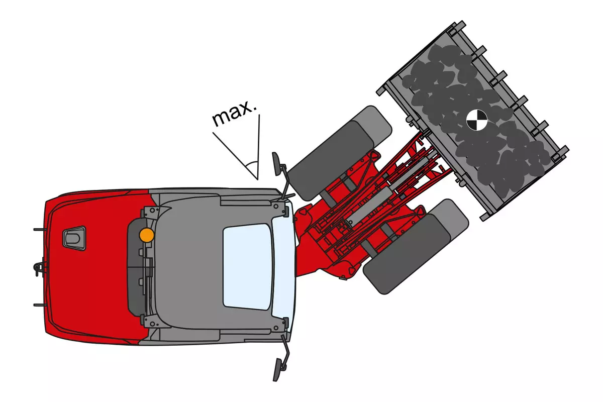
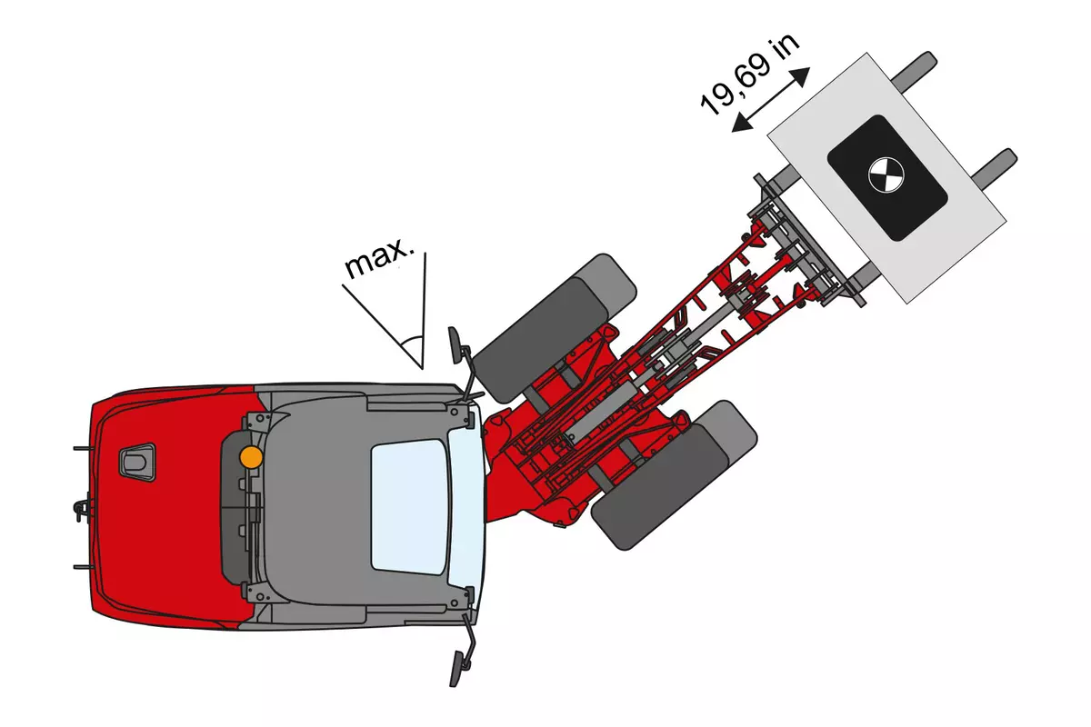
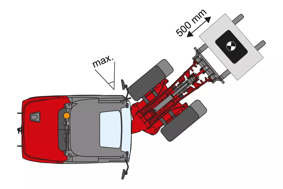
Good to know: Tipping loads determined in the buckled state are highly dependent on the buckling angle of the machine. Weidemann determines these values in the fully folded state. When comparing with other manufacturers, please note the kink angle used!
When comparing tipping loads and lift capacities from different manufacturers, make sure that they have been determined in accordance with the ISO 14397-1 and 2 standards!
General Information
Attention: The tipping load changes depending on the various equipment features of a machine (e.g. operator’s platform/cab, rear weight, engine, tires, etc.). The net weight of the various attachments naturally also plays a role here.
Important to note
Good to know: Tipping loads determined in the buckled state are highly dependent on the buckling angle of the machine. Weidemann determines these values in the fully folded state. When comparing with other manufacturers, please note the kink angle used!
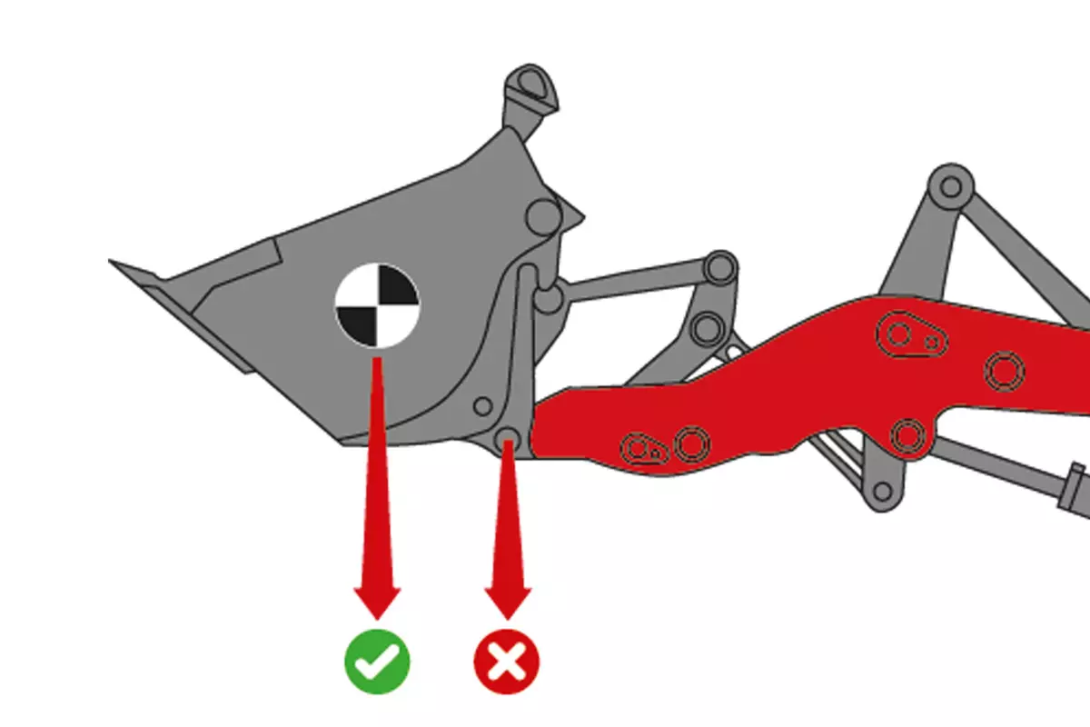
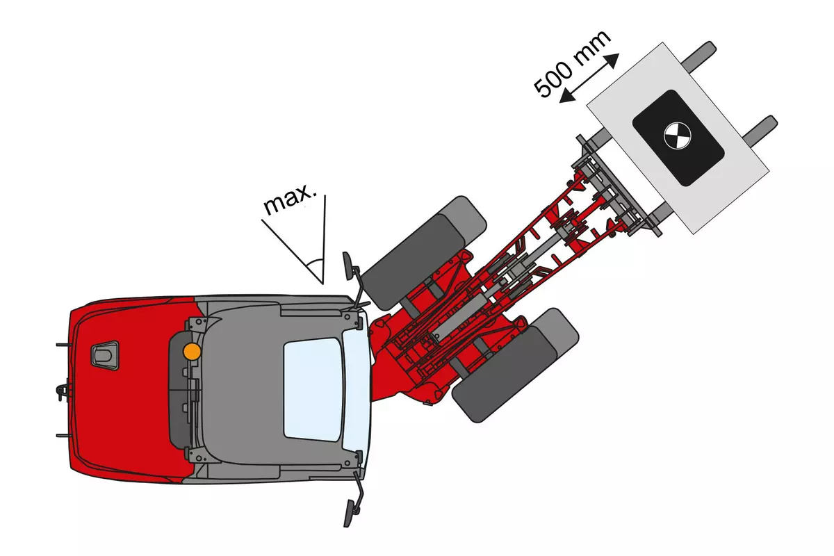
Weidemann determines these values in accordance with the standard at the center of gravity of the bucket – not at the pivot point!
|
|
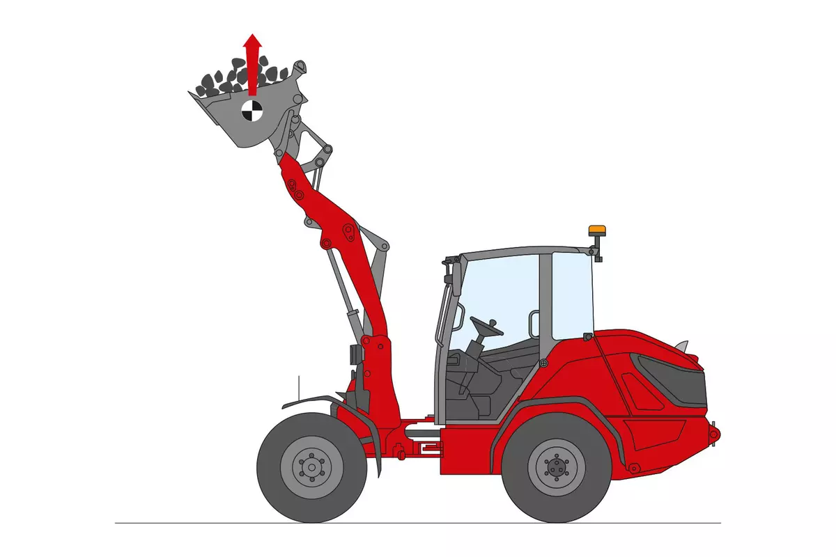
The maximum lift capacity in the bucket’s center of gravity is measured by Weidemann as follows:
|
|
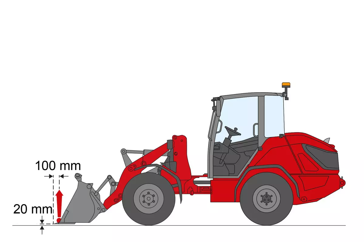
The maximum tear out force on the below bucket edge is measured by Weidemann according to the standard ISO 14397-2, this means:
|
|
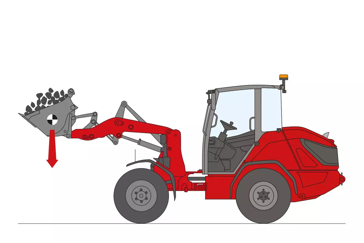
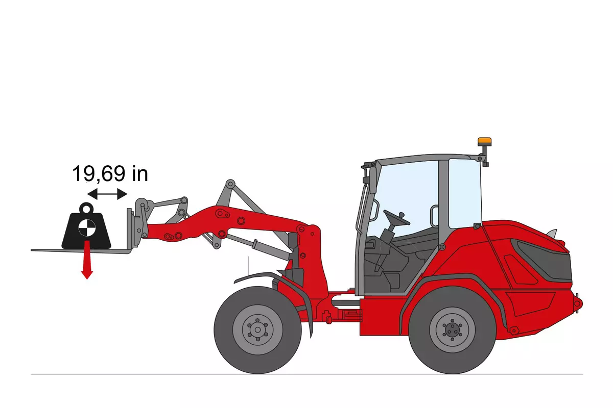
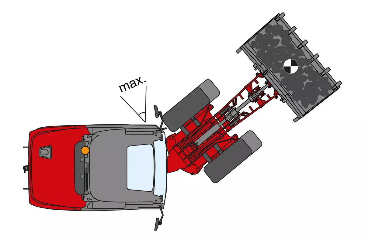
The maximum load weight of a machine is known as the tipping load. This is achieved when the rear wheels of the machine lose contact with the ground. The tipping load is measured by Weidemann according to the standard ISO 14397-1, this means:

|
|
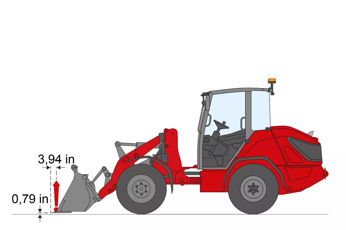
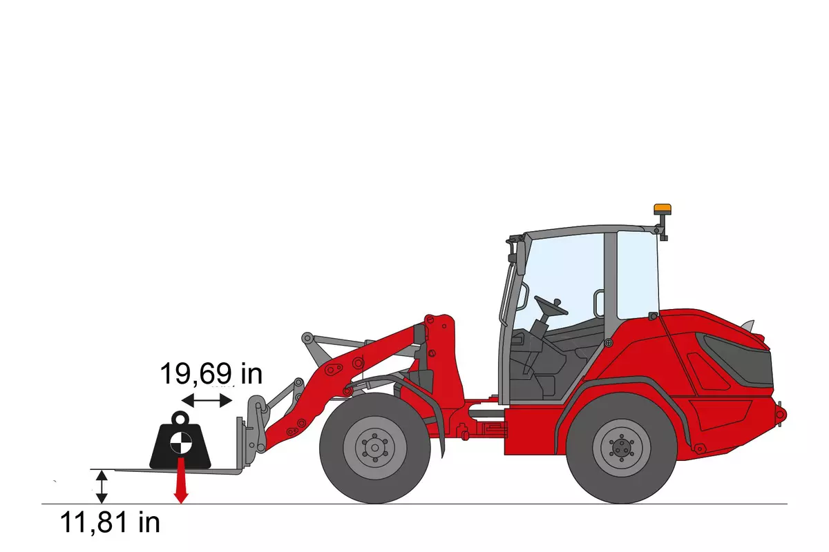
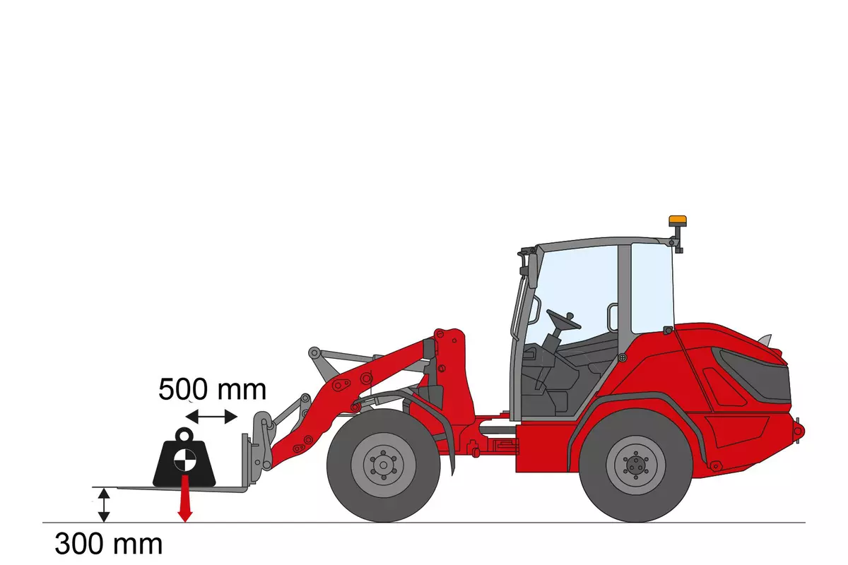
The maximum load weight of a machine is known as the tipping load. This is achieved when the rear wheels of the machine lose contact with the ground. The tipping load in lowest position is measured by Weidemann as follows:


|
|
The maximum load weight of a machine is known as the tipping load. This is achieved when the rear wheels of the machine lose contact with the ground. The tipping load is measured by Weidemann according to the standard ISO 14397-1, this means:

|
|
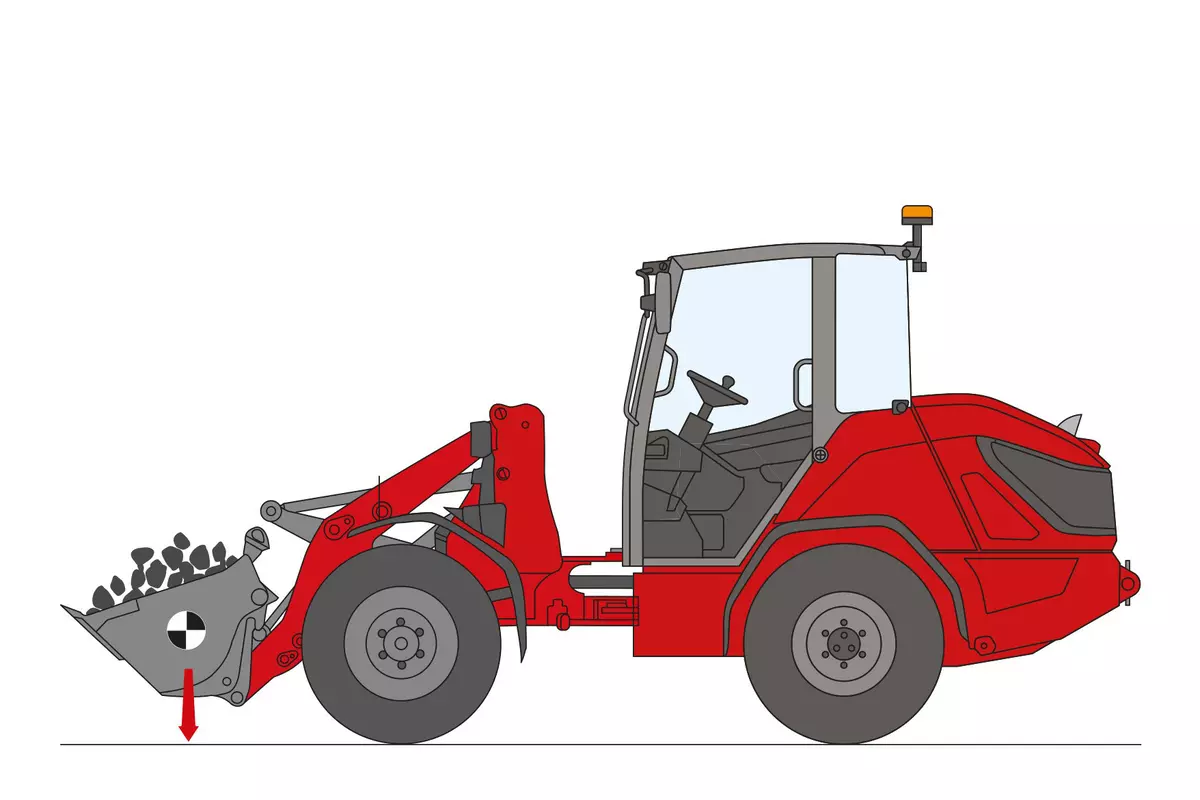
The maximum load weight of a machine is known as the tipping load. This is achieved when the rear wheels of the machine lose contact with the ground. The tipping load in transport position is measured by Weidemann as follows:
|
When the loader is used in accordance with the intended purpose, the whole body vibrations vary from below 0.5 m/s² up to a short-term maximum value.
It is recommended to use the values specified in the table when calculating the vibration values according to ISO/TR 25398:2006. In doing so, the actual application conditions are to be taken into consideration.
Telehandlers, like wheel loaders, are to be classified by operating weight.
Hand-arm vibrations: The hand-arm vibrations are no more than 2.5 m/s²
Whole-body vibrations: This machine is equipped with an operator’s seat that meets the requirements of EN ISO 7096:2000.
| Type of loader | Typical operating conditions | Mean value [m/s2] | Standard deviation (s) in [m/s2] | ||||||
|
| ||||||||
| Compact wheel loader (operating weight < 4500 kg) | Load & carry (load and transport work) |
|
| ||||||
| Wheel loader (operating weight > 4500 kg) | Load & carry (load and transport work) |
|
| ||||||
| Application in extraction (harsh application conditions) |
|
| |||||||
| Delivery drive |
|
| |||||||
| V-operation |
|
|